任意波形発生器モジュール
概要
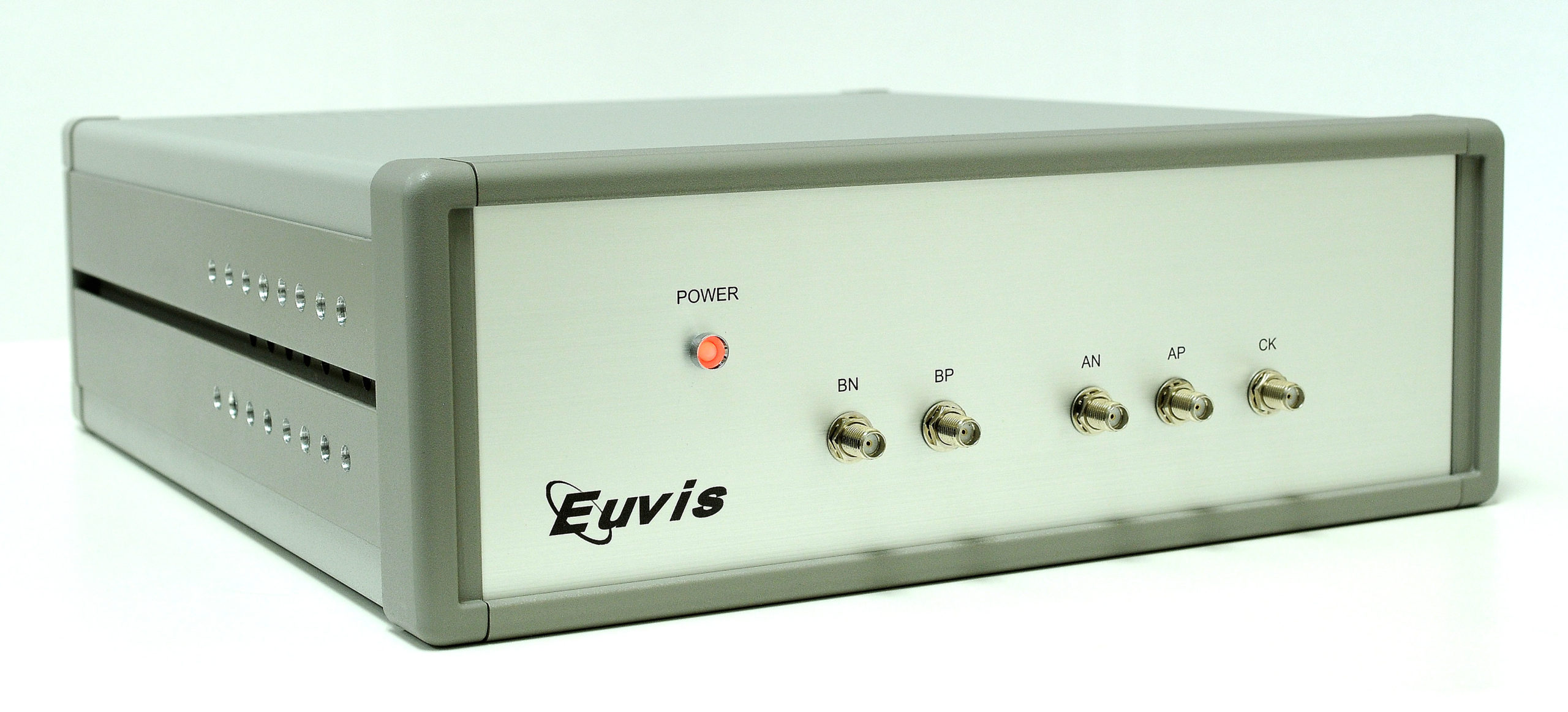
The Euvis AWG modules generate arbitrary CW waveforms with sampling rates up to 8 GSPS. The on-board SRAM's/DRAM's provide up to 8M/1G x 12-bit data memory. The AWG modules can be controlled by a PC via a USB or PCIe interface. The sole RF input is a single-ended clock source, which can be operated up to 4 GHz. The RF outputs of the module are comprised of differential analog outputs with 50-ohm back terminations. The modules accept high-speed trigger signals and generate synchronization outputs and programmable marker signals. The waveform generation can be in continuous or burst/pulse mode. The waveform contents can be dynamically changed using the user page selection. The companion API provides interfaces software development.
Ordering and Pricing Information
For pricing information, please visit Pricing.
For formal quotations, availabilities, and quantity-specific orders, please contact us
Key Features
- 12-bit DAC with 10-bit linearity
- Clock rate up to 5 GHz
- Sampling rate up to 8 Gsps
- up to 8M/1G 12-bit words memory depth with multi-page configuration
- Up to 2/256 millisecond chirping waveform at maximum clock rate
- Accepts external trigger and generates programmable marker signal
- Programmable cyclic length
- PCIe / USB interfaces
- 12V power supply
- User-friendly input data formats and various built-in waveforms
- Companion API and software drivers for easy system development
Applications
The flexibility of Euvis AWG modules to generate arbitrary patterns with high sample rates, dynamic page selection, and continuous or burst mode operation allow the AWG to be used for a variety of applications, such as:
- Linear Frequency Modulation (LFM) and chirping
- Frequency Modulated Continuous-wave radar (FMCW)
- Agile LO frequency synthesis
- Electronic warfare
- RF signal source generation
- Fast frequency hopping
- VSAT satellite communications
- Test and measurement equipment
仕様
| Parameter | AWG414 | AWG474 | AWG872 |
|---|---|---|---|
| DAC Resolution bits | 12 | 10 | 11 |
| Output Data Rate (GSPS) | 4 x 2 | 4 x 2 | 8 x 2 |
| Input Clock Frequency (GHz) | 4 | 4 | 4 |
| Maximum Waveform Length (samples) | 4M x 2 | 1G x 2 | 8M x 2 |
| Interface | USB | USB | USB |
| Minimum Waveform Length, continuous mode (samples) | 128 | 128/CH | 256 |
| Minimum Waveform Length burst mode, (samples) | 1024 | 1024 | 1536 |
| Number of Markers | 1 | 2 | 3 |
| Minimum Marker Length (samples) | 32 | 32 | 64 |
Multiple AWG's Synchronization:
Multiple AWG's can be operated to generate synchronized waveforms. The synchronization requires:
[1] All AWG's use the same clock source, or use clock sources phase-locked to each other. If use internal clock, all AWG's must use the same reference clock.
[2] All AWG's use the same trigger signal.
[3] The trigger signal is phased-locked (aligned) to the /32 clock. The SYNCO signal is a /32 clock, which can be used to phase lock the trigger signal.
[4] Fine adjustment can be done by specifying the delay in common parameters to further minimize the relative delay of AWG's outputs.
For detais, please see synchronization.
Waveform Generation Modes:
The module can be run in three waveform generation modes: Free Run/Continuous mode, Triggered Free Run mode and Triggered Burst Mode.
Free Run / Continuous Mode
In Free Run mode, the module starts waveform generation by a Restart command from the GUI or API-based applications. Once the waveform starts, the module repeats the waveform continuously. There is no latency between two consecutive waveforms. The following waveform starts right after the end of the preceding waveform. The waveform generation can be aborted by an Abort command from the GUI or API-based applications.
Triggered Free Run Mode
In Triggered Free Run mode, the operation manner is similar to that in Free Run mode except for the start of waveform. The waveform generation is initiated by a trigger signal. In order to accept the upcoming trigger signals, the module has to be armed prior the instance of the trigger signals. Trigger signals happening before the module is armed will be ignored. An Arm command from the GUI or API-based applications can be used to arm the module. Once the module is armed, it waits for the trigger signal. The waveform generation starts after the falling edge of the trigger signal. The trigger signal can be mainly applied via the TRIGGER SMA connector or provided by a command Trigger via the GUI or API-based applications.
Triggered Burst Mode
In Triggered Burst mode, the module starts waveform generation when it is armed and receives the trigger signal as in the Triggered Free Run mode. Instead of repeating continuously, the waveform starts, repeats, and stops after finite repetitions. The number of the repetitions can be specified by a property Loop Count via the GUI or the API-based applications. The Loop Count can be set from 1 to 255. Similarly, trigger signals happening before the waveform stops will be ignored. Once the waveform stops, the module will arm itself automatically and wait for the next trigger signal.